Digital Audio Synthesis for Dummies: Part 3
Efficiently streaming audio to speakers on embedded systems (with examples in STM32).
Slap a timer, DMA, and DAC together, and BAM—non-blocking audio output!
— TrebledJ, 2022
Ah… embedded systems—the intersection of robust hardware and versatile software.

This is the third (and culminating) post in a series on digital audio synthesis; but the first (and only?) post touching embedded hardware. In the first post, we introduced basic concepts on audio processing. In the second post, we dived into audio synthesis and generation. In this post, we’ll discover how to effectively implement an audio synthesiser and player on an embedded device by marrying hardware (timers, DACs, DMA) and software (double buffering plus other optimisations).1
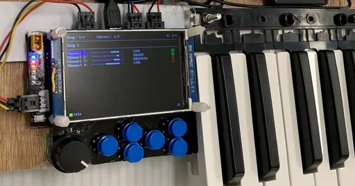
To understand these concepts even better, we’ll look at examples on an STM32. These examples are inspired from a MIDI keyboard project I previously worked on. I'll be using an STM32F405RGT board in the examples. If you plan to follow along with your own board, make sure it's capable of timer-triggered DMA and DAC. An oscilloscope would also be handy for checking DAC output.
This post is much longer than I expected. My suggested approach of reading is to first gain a high-level understanding (possibly skipping the nitty gritty examples), then dig into the examples for details.
Timers ⏰
It turns out kitchens and embedded systems aren’t that different after all! Both perform input and output, and both have timers! Who knew?
Tick Tock
Timers in embedded systems are similar to those in the kitchen: they tick for a period of time and signal an event when finished. However, embedded timers are much fancier than kitchen timers, making them immensely useful in various applications. They can trigger repeatedly (via auto-reload), count up/down, and be used to generate rectangular (PWM) waves.
 Timers have various applications, such as to count signals. (Source: EmbeddedTutor2)
So what makes timers tick?
The MCU clock!
The MCU clock is the backbone of a controller. It controls the processing speed and pretty much everything!—timers, ADC, DAC, communication protocols, and whatnot.
The clock runs at a fixed frequency (168MHz on our board). By dividing against it, we can achieve lower frequencies.
 By using different prescalers, we can achieve lower frequencies. (Source: EmbeddedTutor2)
The following diagram illustrates how the clock signal is divided on an STM. There are two divisors: the prescaler and auto-reload (aka counter period).

How a timer frequency is derived from the clock signal. (Diagram adapted from uPesy.3)
Here, the clock signal is first divided by a prescaler of 2, then further "divided" by an auto-reload of 6. On every overflow (arrow shooting up), the timer triggers an interrupt. In this case, the timer runs at $\frac{1}{12}$ the speed of the clock.
These interrupts can trigger functionality such as DMA transfers (explored later) and ADC conversions.4 Heck, they can even be used to trigger other timers!
Further Reading:
- How do microcontroller timers work?
- Getting Started with STM32: Timers and Timer Interrupts
- There are more prescalers behind the scenes! (APB2)
Example: Initialising the Timer
Suppose we want to send a stream of audio output. We can use a timer with a frequency set to our desired sample rate.
We can derive the prescaler (PSC) and auto-reload (ARR) by finding integer factors that satisfy the following relationship.
$$ \text{freq}_\text{timer} = \frac{\text{freq}_\text{clock}}{(\text{PSC} + 1) \times (\text{ARR} + 1)} $$
where $\text{freq}_\text{timer}$ is the timer frequency (or specifically in our case, the sample rate), $\text{freq}_\text{clock}$ is the clock frequency.
On our STM32F405, we configured $\text{freq}_\text{clock}$ to the maximum possible speed: 168MHz. If we’re aiming for an output sample rate of 42,000Hz, we’d need to divide our clock signal by 4,000, so that we correctly get $\frac{168,000,000}{4,000} = 42,\!000$. For now, we’ll choose register values of PSC = 0 and ARR = 3999.
Why do we add $+1$ to the PSC and ARR in the relationship above?
On the STM32F4, PSC and ARR are 16-bit registers, meaning they range from 0 to 65,535.5 To save space and enhance program correctness, we assign meaningful behaviour to the value 0.
So in this page, when we say PSC = 0, we actually mean a prescaler divisor of 1.
Why 0 and 3999 specifically?
Other pairs of PSC and ARR can also work. We can choose any PSC and ARR which get us to our desired timer frequency. Play around and try different pairs of PSC and ARR!
Exercises for the reader:
- What is the difference between different pairs, such as
PSC = 0,ARR = 3999vs.PSC = 1,ARR = 1999? (Hint: counter.) - Is there a PSC/ARR pair that is "better"?6
We can use STM32 CubeMX to initialise timer parameters. CubeMX allows us to generate code from these options, handling the conundrum of modifying the appropriate registers.

In CubeMX, we first select a timer on the left. We then enable a channel (here Channel 4) to generate PWM.7 We also set the prescaler and auto-reload so that our timer frequency is 42,000Hz.

Some other settings in CubeMX to check.
Remember to generate code once done.9 CubeMX should generate the following code in main.c:
static void MX_TIM8_Init(void)
{
    // --snip-- Initialise structs. --snip--

    htim8.Instance               = TIM8;
    htim8.Init.Prescaler         = 0;
    htim8.Init.CounterMode       = TIM_COUNTERMODE_UP;
    htim8.Init.Period            = 4000 - 1;
    htim8.Init.ClockDivision     = TIM_CLOCKDIVISION_DIV1;
    htim8.Init.RepetitionCounter = 0;
    htim8.Init.AutoReloadPreload = TIM_AUTORELOAD_PRELOAD_DISABLE;
    if (HAL_TIM_Base_Init(&htim8) != HAL_OK) {
        Error_Handler();
    }

    // --snip-- Initialise the clock source. --snip--

    if (HAL_TIM_PWM_Init(&htim8) != HAL_OK) {
        Error_Handler();
    }

    // --snip-- Initialise other things. --snip--

    HAL_TIM_MspPostInit(&htim8);
}
After initialisation, it's possible to change the timer frequency by setting the prescaler and auto-reload registers like so:
TIM8->PSC = 0;    // Prescaler: 1
TIM8->ARR = 3999; // Auto-Reload: 4000
This is useful for applications where the frequency is dynamic (e.g. playing music with a piezoelectric buzzer), but it's also useful when we're too lazy to modify the .ioc file.
Example: Playing with Timers
STM’s HAL library provides ready-made functions to interface with hardware.
HAL_TIM_Base_Start(&htim8); // Start the timer.
HAL_TIM_Base_Stop(&htim8);  // Stop the timer.
These functions are used to start/stop timers for basic timing and counting applications. Functions for more specialised modes (e.g. PWM) are available in stm32f4xx_hal_tim.h.
Digital-to-Analogue Converters (DACs) 🌉
Let's delve into our second topic today: digital-to-analogue converters (DACs).
Audio comes in several forms: sound waves, electrical voltages, and binary data.

Audio manifests in various forms. DACs transform our signal from the digital realm to the analogue world. (Source: Wikimedia Commons.)
Since representations vastly differ, hence the need for interfaces to bridge the worlds. Between the digital and analogue realms, we have DACs and ADCs as mediators. Generally, DACs are used for output while ADCs are for input.
A Closer Look at DACs
Remember sampling? We took a continuous analogue signal and selected discrete points at regular intervals. An ADC is like a glorified sampler.

While ADCs take us from continuous to discrete, DACs (try to) take us from discrete to continuous. The shape of the resulting analogue waveform depends on the DAC implementation. Simple DACs will stagger the output at discrete levels. More complex DACs may interpolate between two discrete samples to “guess” the intermediate values. Some of these guesses will be off, but at least the signal is smoother.

On our STM board, signal reconstruction is staggered, like old platformer games—not that I've played any. At higher sampling rates, the staggered-ness is less apparent and the resulting curve is smoother.
Example: Initialising the DAC
Let’s return to CubeMX to set up our DAC.

Enable DAC, and connect it to Timer 8 using the trigger setting. Our STM32F405 board supports two DAC output channels. This is useful if we want stereo audio output.

Configure DMA settings for the DAC. We’ll cover DMA later.

Enable interrupts for the DMA. These are needed to trigger DAC sends.
Again, remember to generate code when finished.9 The MX_DAC_Init() function should contain the generated DAC setup code and should already be called in main().
Example: Using the DAC
On our STM32, DAC accepts samples quantised to 8 bits or 12 bits.10 We’ll go with superior resolution: 12 bits!

STM32 offers three different options to quantise and align DAC samples. We’ll only focus on the last option: 12-bit right aligned samples. (Source: RM0090 Reference Manual.8)
For simplicity, let’s start with sending 1 DAC sample. This can be done like so:
// Start the DAC peripheral.
HAL_DAC_Start(&hdac, DAC_CHANNEL_1);

// Set the DAC value to 1024 on Channel 1, 12-bit right-aligned.
HAL_DAC_SetValue(&hdac, DAC_CHANNEL_1, DAC_ALIGN_12B_R, 1024);
This should output a voltage level of $\frac{1024}{2^{12}} = 25\%$ of the reference voltage $V_{\text{REF}}$. Once it starts, the DAC will continue sending that voltage out until we change the DAC value or call HAL_DAC_Stop().
We use DAC_CHANNEL_1 to select the first channel, and use DAC_ALIGN_12B_R to accept 12-bit right-aligned samples.
To fire a continuous stream of samples, we could use a loop and call HAL_DAC_SetValue() repeatedly. Let’s use this method to generate a simple square wave.
An aside. The default HAL_Delay() provided by STM will add 1ms to the delay time—well, at least in my version. I overrode it using a separate definition so that it sleeps the given number of ms.
void HAL_Delay(uint32_t ms)
{
    uint32_t start = HAL_GetTick();
    while ((HAL_GetTick() - start) < ms);
}HAL_DAC_Start(&hdac, DAC_CHANNEL_1);
// Alternate between high (4095) and low (0).
uint8_t high = 1;
while (1) {
uint16_t sample = (high ? 4095 : 0); // max = 4095 = 2^12 - 1.
high = !high;
HAL_DAC_SetValue(&hdac, DAC_CHANNEL_1, DAC_ALIGN_12B_R, sample);
// Delay for 5ms.
HAL_Delay(5);
}This generates a square wave with a period of 10ms, for a frequency of 100Hz.

Oscilloscope view of the signal. Oscilloscopes are very useful for debugging signals, especially periodic ones.
But there are two issues with this looping method:
- Using a while loop blocks the thread, meaning we block the processor from doing other things while outputting the sine wave. We may wish to poll for input or send out other forms of output (TFT/LCD, Bluetooth, etc.).
- Since
HAL_Delay()delays in milliseconds, it becomes impossible to generate complex waveforms at high frequencies, since that requires us to send samples at microsecond intervals.

In the next section, we’ll address these issues by combining DAC with timers and DMA.
Further Reading:
Direct Memory Access (DMA) 💉🧠
The final item on our agenda today! Direct Memory Access (DMA) may seem like three random words strung together, but it’s quite a powerful tool in the embedded programmer’s arsenal. How, you ask?
DMA enables data transfer without consuming processor resources. (Well, it consumes some resources, but mainly for setup.) This frees up the processor to do other things while DMA takes care of moving data. We could use this saved time to prepare the next set of buffers, render the GUI, etc.
DMA can be used to transfer data from memory-to-peripheral (e.g. DAC, UART TX, SPI TX), from peripheral-to-memory (e.g. ADC, UART RX), across peripherals, or across memory. In this post, we're concerned with one particular memory-to-peripheral transfer: DAC.
Further Reading:
Example: DMA with Single Buffering
We'll now try using DMA with a single buffer, see why this is problematic, and motivate the need for double buffering. If you’ve read this far, I presume you’ve followed the previous section by initialising DMA and generating code with CubeMX.

DMA introduces syncing issues. After preparing a second round of buffers, how do we know if the first round has already finished?
As with all processes which depend on a separate event, there are two approaches: polling and interrupts. In this context:
- Polling: Block and wait until the first round is finished, then send.
- Interrupts: Trigger an interrupt signal when transfer finishes, and start the next round inside the interrupt handler.
Which approach to choose depends on your application.
In our examples, we’ll poll to check if DMA is finished:
while (HAL_DAC_GetState(&hdac) != HAL_DAC_STATE_READY)
    ;
With DMA, we’ll first need to buffer an array of samples. Our loop will run like this:
- Buffer samples.
- Wait for DMA to be ready.
- Start the DMA.
Do you notice a flaw in this approach? After starting DMA, we start buffering samples on the next iteration. We risk overwriting the buffer while it’s being sent.
Let’s try to implement it anyway and play a simple 440Hz sine wave.
#include <math.h>  // M_PI, sin

#define SAMPLE_RATE 42000
#define BUFFER_SIZE 1024
#define FREQUENCY   440

uint16_t buffer[BUFFER_SIZE];
uint32_t t = 0; // Time (in samples).

// Start the timer.
HAL_TIM_Base_Start(&htim8);

while (1) {
    // Prep the buffer.
    for (int i = 0; i < BUFFER_SIZE; i++, t++) {
        float val = sin(2 * M_PI * FREQUENCY * t / SAMPLE_RATE);
        buffer[i] = 2047 * val + 2047; // Scale the value from [-1, 1] to [0, 2^12-1).
    }

    // Wait for DAC to be ready, so that the buffer can be modified on the next iteration.
    while (HAL_DAC_GetState(&hdac) != HAL_DAC_STATE_READY)
        ;

    // Start the DMA.
    HAL_DAC_Start_DMA(&hdac, DAC_CHANNEL_1, (uint32_t*)buffer, BUFFER_SIZE, DAC_ALIGN_12B_R);
}
The results? As expected, artefacts (nefarious little glitches) invade our signal, since our buffer is updated during DMA transfer. This may result in unpleasant clicks from our speaker.

Prep, wait, start, repeat. Artefacts distort the signal from time to time.
But what if we prep, then start, then wait? This way, the buffer won't be overwritten; but this causes the signal to stall while prepping.11
.")
Prep, start, wait, repeat. The signal stalls (shown by horizontal lines) because the DAC isn’t updated while buffering.
To resolve these issues, we'll unleash the final weapon in our arsenal.
Example: DMA with Double Buffering
We saw previously how a single buffer spectacularly fails to deal with "concurrent" buffering. With double buffering, we introduce an additional buffer. While one buffer is being displayed/streamed, the other buffer is updated. This ensures our audio can be delivered in one continuous stream.
In code, we’ll add another buffer by declaring uint16_t[2][BUFFER_SIZE] instead of uint16_t[BUFFER_SIZE]. We’ll also declare a variable curr (0 or 1) to index which buffer is currently available.
uint16_t buffers[2][BUFFER_SIZE]; // New: add a second buffer.
uint8_t curr = 0;                 // Index of current buffer.
uint32_t t   = 0;

// Start the timer.
HAL_TIM_Base_Start(&htim8);

while (1) {
    uint16_t* buffer = buffers[curr]; // Get the buffer being written.

    // --snip-- Same as before...
    // Prep the buffer.
    // Wait for DAC to be ready.
    // Start the DMA.
    // --snip--

    // Point to the other buffer, so that we
    // prepare it while the previous one
    // is being sent.
    curr = !curr;
}
Now our 440Hz sine wave is unblemished!

Waveform of a pure 440Hz sine tone.
Double buffering is also used for video and displays, where each buffer stores a 2D frame instead of a 1D signal.
Example: Playing Multiple Notes with DMA and Double Buffering 🎶
With some minor changes, we can make our device generate audio for multiple notes. Let’s go ahead and play an A major chord!12
// Prep the buffer.
uint16_t* buffer = buffers[curr];
for (int i = 0; i < BUFFER_SIZE; i++, t++) {
    // Compute value for each note.
    float a = sin(2 * M_PI * 440 * t / SAMPLE_RATE);
    float cs = sin(2 * M_PI * 554.37 * t / SAMPLE_RATE);
    float e = sin(2 * M_PI * 659.25 * t / SAMPLE_RATE);

    float val = (a + cs + e) / 3;  // Sum and normalise to [-1, 1].
    buffer[i] = 2047 * val + 2047; // Map [-1, 1] to [0, 2^12-1).
}
If you flash the above code and feed the output to an oscilloscope, you may find it doesn’t really work. Our signal stalls, for similar reasons as before.
Even with DMA, stalls may occur. This is usually a sign that buffering (and other processes) consume too much time. In this case, breaks in the data occur—the stream is no longer continuous, because the buffer doesn't finish prepping on time.
Optimisations 🏎
So our code is slow. How do we speed it up?
Here are a few common tricks:
Precompute constants.
Instead of computing
2 * M_PI * FREQUENCY / SAMPLE_RATEevery iteration, we can precompute it before the loop, saving many arithmetic instructions.// Precompute a factor of the 440Hz signal. float two_pi_f_over_sr = 2 * M_PI * FREQUENCY / SAMPLE_RATE; while (1) { // Prep the buffer. uint16_t* buffer = buffers[curr]; for (int i = 0; i < BUFFER_SIZE; i++, t++) { // Use the precomputed value... buffer[i] = 2047 * sin(two_pi_f_over_sr * t) + 2047; } // ... }Math functions such as
sincan be computationally expensive, especially when used a lot. By caching the waveform in a lookup table, we can speed up the process of computing samples.Increase the buffer size.
By increasing the buffer size, we spend less overhead switching between tasks.
Decrease the sample rate.
If all else fails, we can decrease the load by compromising the sample rate, say from 42000Hz to 21000Hz. With a buffer size of 1024, that means we’ve gone from a constraint of $\frac{1,024}{42,000} = 24.4$ms to $\frac{1,024}{21,000} = 48.8$ms per buffer.
To avoid complicating things, I lowered the sample rate to 21000Hz. This means changing the auto-reload register to 7999, so that our timer frequency is $$\frac{168,000,000}{(0 + 1) \times (7,999 + 1)} = 21,\!000\text{Hz.}$$
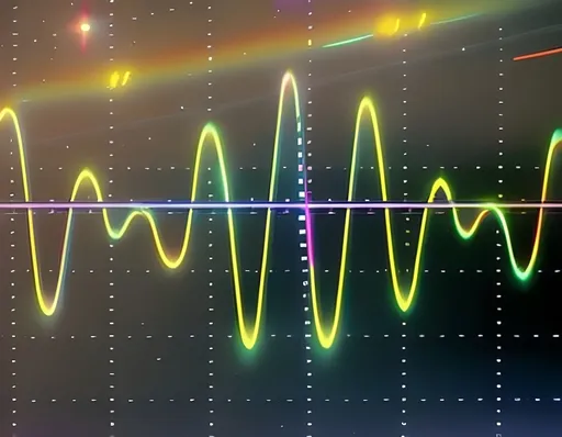
TIM8->ARR = 7999;After all this hassle, we get a beautiful chord.

A nifty waveform of an A major chord (440Hz + 554.37Hz + 659.25Hz).
Recap 🔁
By utilising both hardware and software, we reap the benefits of parallel processing while implementing an efficient, robust audio application. On the hardware side, we explored:
- Timers, which are an useful and inexpensive way to trigger actions at regular intervals.
- DACs, which enable us to communicate with a speaker by translating digital samples into analogue signals.
- DMA, which enables data transfer with minimal processor resources. This way, we can process other things while streaming audio.
In software, we explored:
- Double buffering, a software technique for buffering data to achieve continuous or faster output.
- Various optimisations, which enable us to squeeze more processing into our tiny board.
When combined, we save processing resources, which can possibly be spent on additional features.
In case you want to go further, here are some other things to explore:
- Generating stereo audio. We’ve generated audio for Channel 1. What about stereo audio for Channel 2? If you’re using reverb effects and wish for a fuller stereo sound, you’ll need an extra pair of buffers (and more processing!).
- Streaming via UART (+ DMA).
- Using SIMD instructions to buffer two (or more?) samples at a time.
- Other assembly-level bit-hacking tricks.
- RTOS for multitasking.
- Other boards or hardware with specialised audio features.
Hope you enjoyed this series of posts! Leave a comment if you like to see more or have any feedback!
Full Code
The complete code for DMA with double buffering has been uploaded as a GitHub Gist. It hasn't been fully optimised yet. I'll leave that as an exercise for the reader.
Footnotes
Each of these components (especially hardware) deserve their own post to be properly introduced; but for the sake of keeping this post short, I’ll only introduce them briefly and link to other resources for further perusal. ↩︎
How do microcontroller timers work? – A decent article on timers. Diagrams are in French though. ↩︎
The extent of timer events depends on hardware support. Timers can do a lot on ST boards. For other brands, you may need to check the datasheet or reference manual. ↩︎
Some other timers have 32-bit ARR registers. But eh, we can achieve a lot with just 16-bit ones. ↩︎
What is the difference between pairs of prescaler/auto-reload, such as
PSC = 0,ARR = 3999vs.PSC = 1,ARR = 1999?
Indeed, given a fixed clock frequency, the same timer frequency will be generated (since the divisor is the same: 2000). However, the difference lies in the counter. Recall each step of auto-reload equals a step of the counter.
The counter is used in calculating the on-time (or duty cycle). By using a higherARR, we gain a higher resolution in the counter, which allows us to say, control servos with finer granularity. Thus, a lower prescaler is often preferred.
Of course, different vendors may implement timers differently or have different features attached to timer peripherals. Other considerations may come into play, depending on the vendor and your application. ↩︎We chose Timer 8 (with Channel 4) because it's an advanced control timer (a beefy boi!), capable of a lot, though probably overkill for our simple examples. The timer and channel you use depends on your STM board and model. If you’re following along with this post, make sure to choose a timer which has DMA generation. When in doubt, refer to the reference manual.8 ↩︎
STM's Official Reference Manual for F405/F415, F407/F417, F427/F437, F429/F439 boards. Definitely something to refer to if you’re working on one of those boards. ↩︎ ↩︎
In CubeMX, you can generate code by choosing the Project > Generate Code menu option. Keep in mind that only code between
USER CODE BEGINandUSER CODE ENDcomments will be preserved by ST's code generator. ↩︎ ↩︎There are pros to using 8-bit or 12-bit DAC. 8-bit conversion is faster, whereas 12-bit offers higher resolution. To slightly complicate things, the 12-bit DAC option on our STM32 can be aligned either left or right. That is, we can choose whether our data takes up the first 12 bits or last 12 bits on a 16-bit (2-byte) space. Alignment exists to save you a shift operation, which depends on your application. ↩︎
Not sure if stall is the right word. Let me know if there's a better one. ↩︎
I love minor chords too, but it's not appropriate to play A minor. I'll see myself out. Hope you enjoyed the read. ↩︎
TrebledJ


Passionate problem-solver, software engineer, infosec enthusiast, and amateur music composer. I enjoy teaching others and thrive on learning new things. When not immersed in programming, I can be found taking walks, reflecting on life, and occasionally indulging in CTF challenges.
Related Posts

Digital Audio Synthesis for Dummies: Part 1
An introductory discourse on audio processing. What makes audio tick?